Note
Go to the end to download the full example code
MAPDL 2D 平面应力集中分析#
本教程展示了如何使用 PyMAPDL 确定和验证 “应力集中系数” ,先使用二维平面单元建模,然后使用三维单元进行验证。
首先,将 MAPDL 作为服务启动。
import matplotlib.pyplot as plt
import numpy as np

from ansys.mapdl.core import launch_mapdl

mapdl = launch_mapdl()
Element Type and Material Properties#
本示例将使用 PLANE183 单元,因为只要将其 KEYOPTION 3 设置为 3 并提供厚度,就可以使用平面单元对薄板进行建模。
# 本例将使用国际单位制。

mapdl.prep7()
mapdl.units("SI")  # SI - International system (m, kg, s, K).

# 定义厚度为 PLANE183 的单元类型
mapdl.et(1, "PLANE183", kop3=3)
mapdl.r(1, 0.001)  # 厚度为 0.001 米

# 定义材料(SI 中的标准钢)
mapdl.mp("EX", 1, 210e9)  # Elastic moduli in Pa (kg/(m*s**2))
mapdl.mp("DENS", 1, 7800)  # Density in kg/m3
mapdl.mp("NUXY", 1, 0.3)  # Poisson's Ratio

# 列出当前定义的材料属性
print(mapdl.mplist())
LIST MATERIALS        1 TO        1 BY        1
  PROPERTY= ALL

 MATERIAL NUMBER        1

      TEMP        EX
               0.2100000E+12

      TEMP        NUXY
               0.3000000

      TEMP        DENS
                7800.000
Geometry#
创建一个矩形带孔板。要正确近似无限板,最大应力必须发生在远离板边缘的地方。长宽系数可以近似实现这一点。
length = 0.4
width = 0.1

ratio = 0.3  # diameter/width
diameter = width * ratio
radius = diameter * 0.5


# 创建矩形
rect_anum = mapdl.blc4(width=length, height=width)

# 在矩形中间创建一个圆形
circ_anum = mapdl.cyl4(length / 2, width / 2, radius)

# 请注意 pymapdl 是如何解析输出并返回每条命令创建的 area 编号的。
# 这可以用来对这些 area 执行布尔操作,将圆从矩形中剪切出来。
plate_with_hole_anum = mapdl.asba(rect_anum, circ_anum)

# 注意这里直接返回了执行布尔减操作后,得到的带孔矩形板的图素编号(如下:3),太方便了啊。 ————ff
print(plate_with_hole_anum)
3
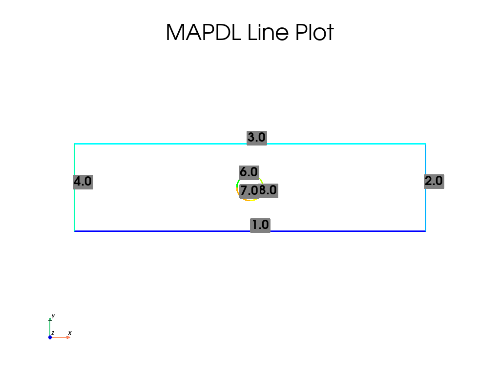
最后,绘制平板的线条
mapdl.lplot(cpos="xy", line_width=3, font_size=26, color_lines=True, background="w")

这里关于详细具体的 **kwargs 参数介绍,见 general_plotter() 。
Meshing#
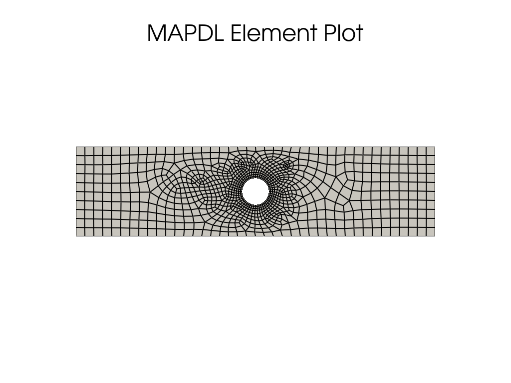
通过为孔附近的线条设置 LESIZE ,为网格全局大小设置 ESIZE ,在孔附近使用较高的密度对薄板进行网格划分,而在板材的其余部分使用较低的密度。
# 线条编号可通过使用 ``lplot`` 检查来确定

# 确保孔周围有 50 个单元
hole_esize = np.pi * diameter / 50  # 0.0002
plate_esize = 0.01

# 增加中心网格的密度
mapdl.lsel("S", "LINE", vmin=5, vmax=8)
mapdl.lesize("ALL", hole_esize, kforc=1)
mapdl.lsel("ALL")

# 减小网格扩张面积。这样可以确保孔洞附近的网格保持精细。
mapdl.mopt("EXPND", 0.7)  # default 1

mapdl.esize(plate_esize)
mapdl.amesh(plate_with_hole_anum)
mapdl.eplot(
    vtk=True,
    cpos="xy",
    show_edges=True,
    show_axes=False,
    line_width=2,
    background="w",
)

Boundary Conditions#
在 X 方向固定板的左侧,并在 X 正方向设置 1 kN 的力。
# 固定左侧。
mapdl.nsel("S", "LOC", "X", 0)
mapdl.d("ALL", "UX")

# 在板的左侧 Y 方向固定一个节点。
# 否则,网格将被允许在 Y 方向移动,成为不适当的约束网格。
mapdl.nsel("R", "LOC", "Y", width / 2)
assert mapdl.mesh.n_node == 1
mapdl.d("ALL", "UY")

# 在平板右侧施加一个力。
# 在本例中,我们选择了薄板最右侧的节点。
mapdl.nsel("S", "LOC", "X", length)

# 确认只选择了与边长相等的节点:
assert np.allclose(mapdl.mesh.nodes[:, 0], length)

# 接下来,为这些节点耦合 DOF。
# 这样,我们就可以为一个节点提供一个力,而这个力将分散到这个耦合集的所有节点上。
mapdl.cp(5, "UX", "ALL")

# 在该组中选择一个节点,并对其施加一个力。
# 我们使用 "R" 从当前节点组中重新选择。
mapdl.nsel("R", "LOC", "Y", width / 2)
mapdl.f("ALL", "FX", 1000)

# 最后,请务必再次选择所有节点,以求解整个 solution
mapdl.allsel(mute=True)
Solve the Static Problem#
求解静力学问题
mapdl.solution()
mapdl.antype("STATIC")
output = mapdl.solve()
mapdl.finish()
print(output)
*** NOTE ***                            CP =       1.562   TIME= 22:16:45
 The automatic domain decomposition logic has selected the MESH domain
 decomposition method with 2 processes per solution.

 *****  MAPDL SOLVE    COMMAND  *****

 *** NOTE ***                            CP =       1.562   TIME= 22:16:45
 There is no title defined for this analysis.

 *** SELECTION OF ELEMENT TECHNOLOGIES FOR APPLICABLE ELEMENTS ***
                ---GIVE SUGGESTIONS ONLY---

 ELEMENT TYPE         1 IS PLANE183 WITH PLANE STRESS OPTION. NO SUGGESTION IS
 AVAILABLE.


 *** MAPDL - ENGINEERING ANALYSIS SYSTEM  RELEASE 2023 R1          23.1     ***
 Ansys Mechanical Enterprise
 20120530  VERSION=WINDOWS x64   22:16:45  JAN 21, 2024 CP=      1.562


                       S O L U T I O N   O P T I O N S

   PROBLEM DIMENSIONALITY. . . . . . . . . . . . .2-D
   DEGREES OF FREEDOM. . . . . . UX   UY
   ANALYSIS TYPE . . . . . . . . . . . . . . . . .STATIC (STEADY-STATE)
   GLOBALLY ASSEMBLED MATRIX . . . . . . . . . . .SYMMETRIC

 *** NOTE ***                            CP =       1.562   TIME= 22:16:45
 Present time 0 is less than or equal to the previous time.  Time will
 default to 1.

 *** NOTE ***                            CP =       1.562   TIME= 22:16:45
 The conditions for direct assembly have been met.  No .emat or .erot
 files will be produced.


     D I S T R I B U T E D   D O M A I N   D E C O M P O S E R

  ...Number of elements: 1005
  ...Number of nodes:    3165
  ...Decompose to 2 CPU domains
  ...Element load balance ratio =     1.002


                      L O A D   S T E P   O P T I O N S

   LOAD STEP NUMBER. . . . . . . . . . . . . . . .     1
   TIME AT END OF THE LOAD STEP. . . . . . . . . .  1.0000
   NUMBER OF SUBSTEPS. . . . . . . . . . . . . . .     1
   STEP CHANGE BOUNDARY CONDITIONS . . . . . . . .    NO
   PRINT OUTPUT CONTROLS . . . . . . . . . . . . .NO PRINTOUT
   DATABASE OUTPUT CONTROLS. . . . . . . . . . . .ALL DATA WRITTEN
                                                  FOR THE LAST SUBSTEP


 SOLUTION MONITORING INFO IS WRITTEN TO FILE= file.mntr


            **** CENTER OF MASS, MASS, AND MASS MOMENTS OF INERTIA ****

  CALCULATIONS ASSUME ELEMENT MASS AT ELEMENT CENTROID

  TOTAL MASS =  0.30649

                           MOM. OF INERTIA         MOM. OF INERTIA
  CENTER OF MASS            ABOUT ORIGIN        ABOUT CENTER OF MASS

  XC =  0.20000          IXX =   0.1024E-02      IXX =   0.2577E-03
  YC =  0.50004E-01      IYY =   0.1642E-01      IYY =   0.4157E-02
  ZC =   0.0000          IZZ =   0.1744E-01      IZZ =   0.4414E-02
                         IXY =  -0.3065E-02      IXY =  -0.1332E-06
                         IYZ =    0.000          IYZ =    0.000
                         IZX =    0.000          IZX =    0.000


  *** MASS SUMMARY BY ELEMENT TYPE ***

  TYPE      MASS
     1  0.306487

 Range of element maximum matrix coefficients in global coordinates
 Maximum = 1.001299206E+09 at element 401.
 Minimum = 360452396 at element 853.

   *** ELEMENT MATRIX FORMULATION TIMES
     TYPE    NUMBER   ENAME      TOTAL CP  AVE CP

        1      1005  PLANE183      0.000   0.000000
 Time at end of element matrix formulation CP = 1.609375.

 DISTRIBUTED SPARSE MATRIX DIRECT SOLVER.
  Number of equations =        6288,    Maximum wavefront =     42

  Process memory allocated for solver              =     5.136 MB
  Process memory required for in-core solution     =     4.944 MB
  Process memory required for out-of-core solution =     3.136 MB

  Total memory allocated for solver                =    10.194 MB
  Total memory required for in-core solution       =     9.813 MB
  Total memory required for out-of-core solution   =     6.258 MB

 *** NOTE ***                            CP =       1.641   TIME= 22:16:45
 The Distributed Sparse Matrix Solver is currently running in the
 in-core memory mode.  This memory mode uses the most amount of memory
 in order to avoid using the hard drive as much as possible, which most
 often results in the fastest solution time.  This mode is recommended
 if enough physical memory is present to accommodate all of the solver
 data.
 Distributed sparse solver maximum pivot= 1.638913676E+09 at node 391
 UY.
 Distributed sparse solver minimum pivot= 7553313.85 at node 2748 UY.
 Distributed sparse solver minimum pivot in absolute value= 7553313.85
 at node 2748 UY.

   *** ELEMENT RESULT CALCULATION TIMES
     TYPE    NUMBER   ENAME      TOTAL CP  AVE CP

        1      1005  PLANE183      0.016   0.000016

   *** NODAL LOAD CALCULATION TIMES
     TYPE    NUMBER   ENAME      TOTAL CP  AVE CP

        1      1005  PLANE183      0.000   0.000000
 *** LOAD STEP     1   SUBSTEP     1  COMPLETED.    CUM ITER =      1
 *** TIME =   1.00000         TIME INC =   1.00000      NEW TRIANG MATRIX


 *** MAPDL BINARY FILE STATISTICS
  BUFFER SIZE USED= 16384
        0.875 MB WRITTEN ON ASSEMBLED MATRIX FILE: file0.full
        0.688 MB WRITTEN ON RESULTS FILE: file0.rst
Post-Processing#
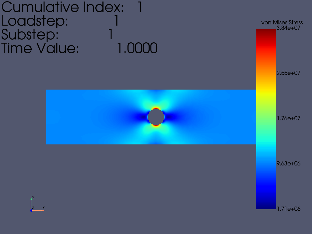
静态结果可以在 MAPDL 内或 MAPDL 外使用 pyansys 进行后处理。本例展示了如何使用 pyansys 结果读取器提取 von Mises 应力并绘制其曲线。
# 从 ``mapdl`` 实例中抓取结果
result = mapdl.result
# 下面这个 fun 是 PyMAPDL Reader 里面的。 ————ff
result.plot_principal_nodal_stress(
    0, # 索引为零的累积结果编号,或包含请求结果(步、子步)的列表。
    "SEQV", # 等效应力
    lighting=False,
    cpos="xy", # The camera position to use. 使用的摄像机位置。
    background="w",
    text_color="k",
    add_text=True, # 控制左上角
)

nnum, stress = result.principal_nodal_stress(0)
von_mises = stress[:, -1]  # von-Mises 应力是最右边的一列

# 必须使用 `nanmax` 获取最大等效应力
max_stress = np.nanmax(von_mises) # 返回数组的最大值或沿坐标轴的最大值。

Compute the Stress Concentration#
应力集中 \(K_t\) 是孔的最大应力与远场应力或远离孔的点的平均截面应力之比。分析时,可以用以下方法计算:
\(\sigma_{nom} = \frac{F}{wt}\)
其中
\(F\) is the force
\(w\) is the width of the plate
\(t\) is the thickness of the plate.
实验中,计算方法是取平板最右侧节点的平均值。
# 我们在这里使用 `nanmean` 获取平均值
mask = result.mesh.nodes[:, 0] == length
far_field_stress = np.nanmean(von_mises[mask])
print("Far field von Mises stress: %e" % far_field_stress)
# 这几乎正好等于 10000000.0 帕的分析值
Far field von Mises stress: 9.999966e+06
由于孔横截面上的预期标称应力会随着孔尺寸的增大而增大,无论应力集中与否, 都必须对应力进行调整,以获得正确的应力。该应力根据宽度与修正截面宽度之比进行调整。
adj = width / (width - diameter) # adjusted
stress_adj = far_field_stress * adj

# 然后,应力集中系数就是最大应力除以调整后的远场应力。
stress_con = max_stress / stress_adj
print("Stress Concentration: %.2f" % stress_con)
Stress Concentration: 2.34
Batch Analysis#
上述脚本可用于计算各种孔径的应力集中。对于每个批处理,MAPDL 都会重置,并生成相应几何体。
def compute_stress_con(ratio):
    """计算带孔钢板在单轴力作用下的应力集中系数。
    """
    mapdl.clear("NOSTART")
    mapdl.prep7()
    mapdl.units("SI")  # SI - International system (m, kg, s, K).

    # define a PLANE183 element type with thickness
    mapdl.et(1, "PLANE183", kop3=3)
    mapdl.r(1, 0.001)  # thickness of 0.001 meters)

    # Define a material (nominal steel in SI)
    mapdl.mp("EX", 1, 210e9)  # Elastic moduli in Pa (kg/(m*s**2))
    mapdl.mp("DENS", 1, 7800)  # Density in kg/m3
    mapdl.mp("NUXY", 1, 0.3)  # Poisson's Ratio
    mapdl.emodif("ALL", "MAT", 1)

    # Geometry
    # ~~~~~~~~
    # Create a rectangular area with the hole in the middle
    diameter = width * ratio
    radius = diameter * 0.5

    # create the rectangle
    rect_anum = mapdl.blc4(width=length, height=width)

    # create a circle in the middle of the rectangle
    circ_anum = mapdl.cyl4(length / 2, width / 2, radius)

    # Note how pyansys parses the output and returns the area numbers
    # created by each command.  This can be used to execute a boolean
    # operation on these areas to cut the circle out of the rectangle.
    plate_with_hole_anum = mapdl.asba(rect_anum, circ_anum)

    # Meshing
    # ~~~~~~~
    # Mesh the plate using a higher density near the hole and a lower
    # density for the remainder of the plate

    mapdl.aclear("all")

    # ensure there are at least 100 elements around the hole
    hole_esize = np.pi * diameter / 100  # 0.0002
    plate_esize = 0.01

    # increased the density of the mesh at the center
    mapdl.lsel("S", "LINE", vmin=5, vmax=8)
    mapdl.lesize("ALL", hole_esize, kforc=1)
    mapdl.lsel("ALL")

    # Decrease the area mesh expansion.  This ensures that the mesh
    # remains fine nearby the hole
    mapdl.mopt("EXPND", 0.7)  # default 1

    mapdl.esize(plate_esize)
    mapdl.amesh(plate_with_hole_anum)

    # Boundary Conditions
    # ~~~~~~~~~~~~~~~~~~~
    # Fix the left-hand side of the plate in the X direction
    mapdl.nsel("S", "LOC", "X", 0)
    mapdl.d("ALL", "UX")

    # Fix a single node on the left-hand side of the plate in the Y direction
    mapdl.nsel("R", "LOC", "Y", width / 2)
    assert mapdl.mesh.n_node == 1
    mapdl.d("ALL", "UY")

    # Apply a force on the right-hand side of the plate.  For this
    # example, we select the right-hand side of the plate.
    mapdl.nsel("S", "LOC", "X", length)

    # Next, couple the DOF for these nodes
    mapdl.cp(5, "UX", "ALL")

    # Again, select a single node in this set and apply a force to it
    mapdl.nsel("r", "loc", "y", width / 2)
    mapdl.f("ALL", "FX", 1000)

    # finally, be sure to select all nodes again to solve the entire solution
    mapdl.allsel()

    # Solve the Static Problem
    # ~~~~~~~~~~~~~~~~~~~~~~~~
    mapdl.solution()
    mapdl.antype("STATIC")
    mapdl.solve()
    mapdl.finish()

    # Post-Processing
    # ~~~~~~~~~~~~~~~
    # grab the stress from the result
    result = mapdl.result
    nnum, stress = result.principal_nodal_stress(0)
    von_mises = stress[:, -1]
    max_stress = np.nanmax(von_mises)

    # compare to the "far field" stress by getting the mean value of the
    # stress at the wall
    mask = result.mesh.nodes[:, 0] == length
    far_field_stress = np.nanmean(von_mises[mask])

    # adjust by the cross sectional area at the hole
    adj = width / (width - diameter)
    stress_adj = far_field_stress * adj

    # finally, compute the stress concentration
    return max_stress / stress_adj
运行批处理并记录应力集中
k_t_exp = []
ratios = np.linspace(0.01, 0.5, 10)
print("    Ratio  : Stress Concentration (K_t)")
for ratio in ratios:
    stress_con = compute_stress_con(ratio)
    print("%10.4f : %10.4f" % (ratio, stress_con))
    k_t_exp.append(stress_con)
Ratio  : Stress Concentration (K_t)
0.0100 :     2.9654
0.0644 :     2.8119
0.1189 :     2.6807
0.1733 :     2.5607
0.2278 :     2.4619
0.2822 :     2.3766
0.3367 :     2.3058
0.3911 :     2.2479
0.4456 :     2.2011
0.5000 :     2.1609
Analytical Comparison#
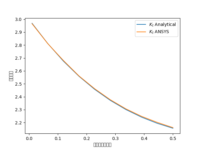
应力集中通常是通过参考各种几何形状的表格结果或多项式拟合得到的。 根据 Peterson 的《应力集中系数》(ISBN 0470048247),单轴拉伸薄板上的孔的解析方程为:
\(k_t = 3 - 3.14\frac{d}{h} + 3.667\left(\frac{d}{h}\right)^2 - 1.527\left(\frac{d}{h}\right)^3\)
Where:
\(k_t\) 是应力集中系数
\(d\) 是圆的直径
\(h\) 是薄板的高度
如下图所示,使用 PLANE183 单元,ANSYS 与该几何形状的已知表格结果非常吻合。 根据板的高度和宽度之间的比例,结果的拟合程度可能会有所不同。
# where ratio is (d/h)
k_t_anl = 3 - 3.14 * ratios + 3.667 * ratios**2 - 1.527 * ratios**3

plt.plot(ratios, k_t_anl, label=r"$K_t$ Analytical")
plt.plot(ratios, k_t_exp, label=r"$K_t$ ANSYS")
plt.legend()
plt.xlabel("孔径与板宽之比")
plt.ylabel("应力集中")
plt.show()

Stop mapdl#
mapdl.exit()
Total running time of the script: (0 minutes 11.177 seconds)